1043 Lab Build A Switch And Router Network
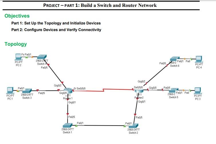
1043 Lab Build A Switch And Router Network - Assign class as the privileged exec encrypted password. This lab provides minimal assistance with the actual commands necessary to configure the router. Assign the device name to the router. This document describes a lab activity to build a network with a router and switch according to the provided topology diagram and addressing table. The topology connects two pcs on different subnets through a router and switch. Assign cisco as the console password and enable login. Initialize and restart the router and switch. You will then configure the devices to match the addressing table. Retrieve hardware and software information from the network devices. My goal is to create a robust home network. You will then configure the devices to match the addressing table. Power on all the devices in the topology. My goal is to create a robust home network. Attach the devices shown in the topology diagram, and cable, as necessary. Console into the router and enable privileged exec mode. Retrieve hardware and software information from the network devices. About press copyright contact us creators advertise developers terms privacy policy & safety how youtube works test new features nfl sunday ticket press copyright. This article seeks to bring solutions by displaying images and providing answers to the questions in the lab for better understanding. You will then configure the devices to match the addressing table. Cable the network as shown in the topology. After the configurations have been saved, you will verify your configurations by testing for network connectivity. After the configurations have been saved, you will verify your configurations by testing for network connectivity. About press copyright contact us creators advertise developers terms privacy policy & safety how youtube works test new features nfl sunday ticket press copyright. This document describes a. You will then configure the devices to match the addressing table. In this packet tracer physical mode (ptpm) activity, you will cable the equipment as shown in the topology diagram. Pc → desktop → ip configuration → type in information from table. This lab provides minimal assistance with the actual commands necessary to configure the router. This document describes a. The topology connects two pcs on different subnets through a router and switch. In this packet tracer physical mode (ptpm) activity, you will cable the equipment as shown in the topology diagram. Meanwhile, the server and other devices in my home lab will be connected to the cisco switch. Your tasks include configuring basic settings on a router and a. Console into the router and enable privileged exec mode. Your tasks include configuring basic settings on a router and a switch using the cisco ios. In this packet tracer physical mode (ptpm) activity, you will cable the equipment as shown in the topology diagram. Attach the devices shown in the topology diagram, and cable, as necessary. After the configurations have. Initialize and reload the router and switch. Initialize and restart the router and switch. This document describes a lab activity to build a network with a router and switch according to the provided topology diagram and addressing table. Power on all the devices in the topology. Meanwhile, the server and other devices in my home lab will be connected to. After the configurations have been saved, you will verify your configurations by testing for network connectivity. Pc → desktop → ip configuration → type in information from table. Click the cisco packet tracer file to get the lab file to follow up with the solution. Assign cisco as the vty password and enable login. This document describes a lab activity. Retrieve hardware and software information from the network devices. Power on all the devices in the topology. Assign static ip information to the pc interfaces. This lab provides minimal assistance with the actual commands necessary to configure the router. This article seeks to bring solutions by displaying images and providing answers to the questions in the lab for better understanding. Pc → desktop → ip configuration → type in information from table. Anyone on the internet can find and access. Attach the devices shown in the topology diagram, and cable, as necessary. This document describes a lab activity to build a network with a router and switch according to the provided topology diagram and addressing table. You will then configure. Cable the network as shown in the topology. You will also configure ipv6 addresses on network page 1 of 4csis 330 devices and hosts. Attach the devices shown in the topology diagram, and cable, as necessary. Click the cisco packet tracer file to get the lab file to follow up with the solution. In this lab, you will cable the. You will then configure the devices to match the addressing table. Cable the network as shown in the topology. Meanwhile, the server and other devices in my home lab will be connected to the cisco switch. Assign the device name to the router. Click the cisco packet tracer file to get the lab file to follow up with the solution. In this packet tracer physical mode (ptpm) activity, you will cable the equipment as shown in the topology diagram. Click the cisco packet tracer file to get the lab file to follow up with the solution. Assign cisco as the console password and enable login. In this lab, you will cable the equipment as shown in the topology diagram. Console into the router and enable privileged exec mode. This document describes a lab activity to build a network with a router and switch according to the provided topology diagram and addressing table. Assign cisco as the vty password and enable login. You will then configure the devices to match the addressing table. The topology connects two pcs on different subnets through a router and switch. About press copyright contact us creators advertise developers terms privacy policy & safety how youtube works test new features nfl sunday ticket press copyright. Power on all the devices in the topology. Cable the network as shown in the topology. Test your knowledge by trying to configure the devices without referring to the content or previous activities. Set up equipment to match the network topology. Attach the devices shown in the topology diagram, and cable, as necessary. After the configurations have been saved, you will verify your configurations by testing for network connectivity.Solved PROJECT PART 1 Build a Switch and Router Network

10.4.4 Lab Build a Switch and Router Network Lab Build a Switch
ECOR 1043 Lab 1 lab write up for lab 1 Lab 1 Introduction to

Lab 2 1043 F22 idk Laboratory Experiment Introduction to Circuit

10.4.4 Packet tracer Build a switch and router network YouTube

Lab Building a Switch and Router Network Sadə şəbəkənin qurulması

Network In Building Diagram With 6 Switches And Four Routers

6.5.1.2 Lab Building a Switch and Router Network YouTube
Lab Building a Switch and Router Network
10.4.4 Lab Build A Switch and Router Network ILM PDF Enrutador
Retrieve Hardware And Software Information From The Network Devices.
My Goal Is To Create A Robust Home Network.
Assign Static Ip Information To The Pc Interfaces.
Pc → Desktop → Ip Configuration → Type In Information From Table.
Related Post: