Building A Circuit With Thermistor
Building A Circuit With Thermistor - Murata’s simsurfing design support tool simplifies the process of designing circuits using thermistors. You’ll want to begin with an empty breadboard with. Thermistors are made so that the resistance changes drastically with temperature so that it can be 100 ohms or more of change per degree! In this article, we'll be talking about the basics of thermistor circuit diagrams and their various applications. A thermistor is made of oxides of metals such as nickel, manganese, cobalt, copper, uranium etc. Now that we have covered the basics of heat sensor circuits and temperature sensors, let’s build a simple heat sensor circuit using an ntc. This video explains how to use simsurfing. This means it automatically regulates temperature or activates a device. This circuit activates an led when it senses This guide will teach you how. This video explains how to use simsurfing. I also researched some more and was able to come. Create a circuit using the waterproof thermistor that will enable you to measure the changes in resistance as the temperature changes. A thermistor is a temperature sensor and is regularly used as a thermostat. This means it automatically regulates temperature or activates a device. This guide will teach you how. For temperature sensing using an ntc thermistor, the resistor, r1, is chosen based on the temperature range and the ntc’s value. In this tutorial, we are making a project of a simple temperature sensor circuit. It is available in a variety of shapes and sizes. Building a heat sensor circuit. For temperature sensing using an ntc thermistor, the resistor, r1, is chosen based on the temperature range and the ntc’s value. Building a heat sensor circuit. Murata’s simsurfing design support tool simplifies the process of designing circuits using thermistors. This means it automatically regulates temperature or activates a device. Now that we have covered the basics of heat sensor circuits. I also researched some more and was able to come. As the temperature changes, the resistance of the. For temperature sensing using an ntc thermistor, the resistor, r1, is chosen based on the temperature range and the ntc’s value. In this tutorial, we are making a project of a simple temperature sensor circuit. This means it automatically regulates temperature or. My basic knowledge tells me that i can just use a resistor, an led to serve as an indicator, a heating coil, and thermistor. Building a heat sensor circuit. As the temperature changes, the resistance of the. A thermistor is made of oxides of metals such as nickel, manganese, cobalt, copper, uranium etc. This video explains how to use simsurfing. A thermistor is a temperature sensor and is regularly used as a thermostat. A thermistor is made of oxides of metals such as nickel, manganese, cobalt, copper, uranium etc. The basics consist of three. This guide will teach you how. As the temperature changes, the resistance of the. As the temperature changes, the resistance of the. Now that we have covered the basics of heat sensor circuits and temperature sensors, let’s build a simple heat sensor circuit using an ntc. Operate within the linear output voltage swing (see. It is available in a variety of shapes and sizes. This circuit activates an led when it senses I also researched some more and was able to come. For temperature sensing using an ntc thermistor, the resistor, r1, is chosen based on the temperature range and the ntc’s value. The basics consist of three. It is available in a variety of shapes and sizes. You’ll want to begin with an empty breadboard with. For temperature sensing using an ntc thermistor, the resistor, r1, is chosen based on the temperature range and the ntc’s value. A thermistor circuit diagram can be the perfect way to get started. This circuit activates an led when it senses Murata’s simsurfing design support tool simplifies the process of designing circuits using thermistors. As the temperature changes, the resistance. A thermistor circuit diagram can be the perfect way to get started. This circuit activates an led when it senses It is available in a variety of shapes and sizes. Thermistors are made so that the resistance changes drastically with temperature so that it can be 100 ohms or more of change per degree! In this video i made a. In this article, we'll be talking about the basics of thermistor circuit diagrams and their various applications. Murata’s simsurfing design support tool simplifies the process of designing circuits using thermistors. The basics consist of three. A thermistor is made of oxides of metals such as nickel, manganese, cobalt, copper, uranium etc. For temperature sensing using an ntc thermistor, the resistor,. This circuit activates an led when it senses This means it automatically regulates temperature or activates a device. A thermistor circuit diagram can be the perfect way to get started. As the temperature changes, the resistance of the. My basic knowledge tells me that i can just use a resistor, an led to serve as an indicator, a heating coil,. This circuit activates an led when it senses A thermistor circuit diagram can be the perfect way to get started. In this tutorial, we are making a project of a simple temperature sensor circuit. Thermistors are made so that the resistance changes drastically with temperature so that it can be 100 ohms or more of change per degree! As the temperature changes, the resistance of the. For temperature sensing using an ntc thermistor, the resistor, r1, is chosen based on the temperature range and the ntc’s value. Create a circuit using the waterproof thermistor that will enable you to measure the changes in resistance as the temperature changes. The basics consist of three. This means it automatically regulates temperature or activates a device. A thermistor is a temperature sensor and is regularly used as a thermostat. Now that we have covered the basics of heat sensor circuits and temperature sensors, let’s build a simple heat sensor circuit using an ntc. Operate within the linear output voltage swing (see. A thermistor is made of oxides of metals such as nickel, manganese, cobalt, copper, uranium etc. My basic knowledge tells me that i can just use a resistor, an led to serve as an indicator, a heating coil, and thermistor. This video explains how to use simsurfing. This guide will teach you how.
Thermistor MOSFET Fan Controller (Circuit construction) Part 2 YouTube

THERMISTOR WITH ARDUINO UNO R3 5 Steps Instructables

Make An Arduino Temperature Sensor Using Thermistor Circuit, 54 OFF

How To make Temperature Sensor circuit Using Thermistor YouTube

How to make Temperature Sensor Switch Using Thermistor YouTube
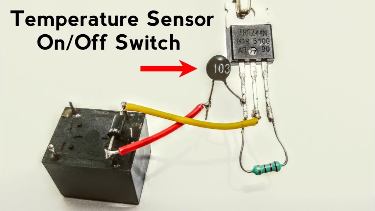
How to Make Temperature Sensor Switch Circuit using Thermistor YouTube

Make an Arduino Temperature Sensor (Thermistor Tutorial)

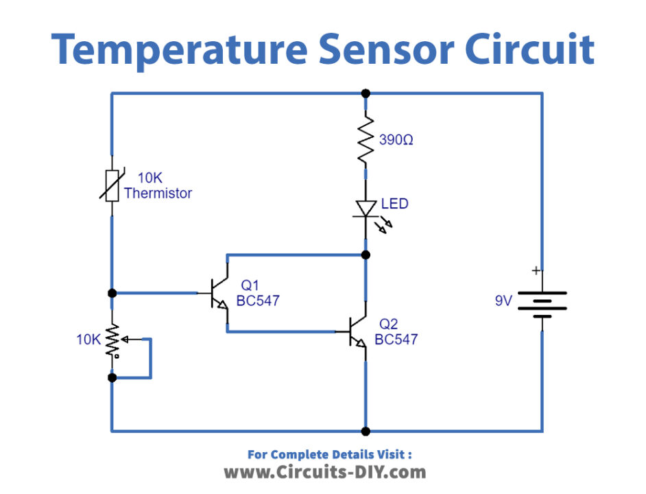
Heat Sensor Circuit using Thermistor & BC547 Transistor Simple
Circuit Diagram Of Using Arduino And A Thermistor Arduino Th

Heat Sensor Circuit using Thermistor
In This Article, We'll Be Talking About The Basics Of Thermistor Circuit Diagrams And Their Various Applications.
I Also Researched Some More And Was Able To Come.
Building A Heat Sensor Circuit.
You’ll Want To Begin With An Empty Breadboard With.
Related Post: