How To Build A Diode Rf Probe
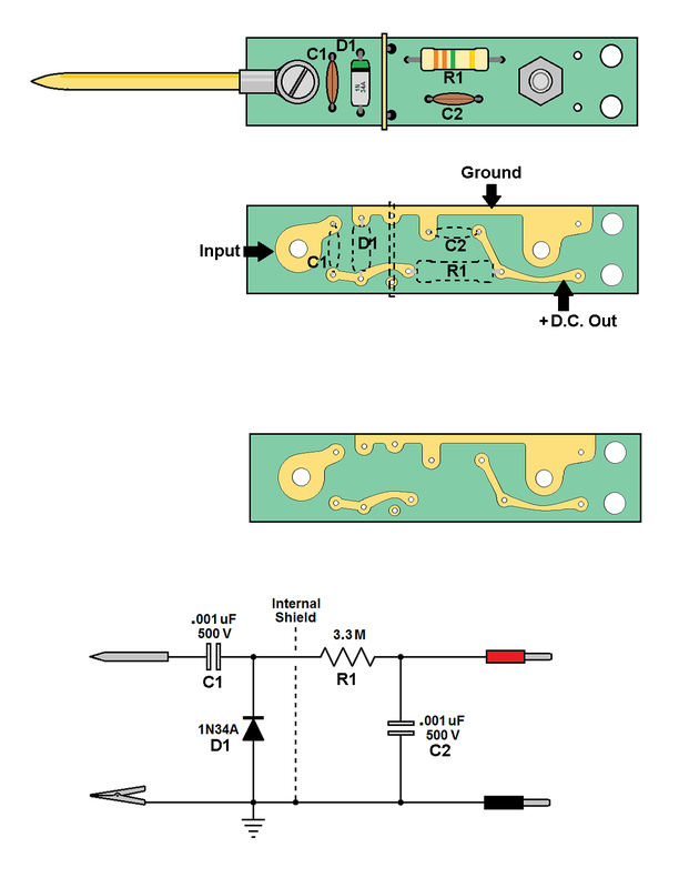
How To Build A Diode Rf Probe - A passive probe works where relative measurements are. In this way it is very easy to measure rf voltages for either testing or. In this article, ham radio operators and arduino enthusiasts of all skill levels get to create a wideband rf signal sniffer based on the analog devices ad8307 logarithmic amplifier, a. The layout is not critical, but do make sure you get. I suggest that you follow the circuit diagram layout to build this on veroboard. Here’s a posting talking about how the. This may not matter for your purposes, but for reading (at least the presence, if not. I’m looking at building a probe to work with my spectrum analyzer where i want to probe the signal chain in a receiver. The experimental setup is depicted in fig. This circuit also appears on the qrpedia posting on rf probes, and apparently is constructed as part of the assembly of the elecraft k2. It is based on an elektor. In this article, ham radio operators and arduino enthusiasts of all skill levels get to create a wideband rf signal sniffer based on the analog devices ad8307 logarithmic amplifier, a. A 1n270, 1n34a or 1n60p are all good choices, with the 1n270 having the highest reverse voltage tolerance. This may not matter for your purposes, but for reading (at least the presence, if not. This circuit also appears on the qrpedia posting on rf probes, and apparently is constructed as part of the assembly of the elecraft k2. These advancements, driven by the needs of military and. I suggest that you follow the circuit diagram layout to build this on veroboard. Here’s a posting talking about how the. A fast switching silicon diode like a 1n4148 will work, but is the least sensitive of them all. A rf probe is a circuit for testing equipment that converts a high frequency signal into a dc voltage. Use your multimeter test lead as a probe. A 1n270, 1n34a or 1n60p are all good choices, with the 1n270 having the highest reverse voltage tolerance. The experimental setup is depicted in fig. A rf probe is a circuit for testing equipment that converts a high frequency signal into a dc voltage. A fast switching silicon diode like a 1n4148. Use your multimeter test lead as a probe. If we observe carefully, the peak level of rf voltage at the tip of the probe is equal to the rectified dc voltage at the cathode of the diode d 1 connected as in the figure. In this way it is very easy to measure rf voltages for either testing or. These. Here’s a posting talking about how the. Use your multimeter test lead as a probe. I suggest that you follow the circuit diagram layout to build this on veroboard. A passive probe works where relative measurements are. It is based on an elektor. It is based on an elektor. A fast switching silicon diode like a 1n4148 will work, but is the least sensitive of them all. Use your multimeter test lead as a probe. If we observe carefully, the peak level of rf voltage at the tip of the probe is equal to the rectified dc voltage at the cathode of the. Use your multimeter test lead as a probe. This circuit also appears on the qrpedia posting on rf probes, and apparently is constructed as part of the assembly of the elecraft k2. The layout is not critical, but do make sure you get. Here’s a posting talking about how the. In this article, ham radio operators and arduino enthusiasts of. These advancements, driven by the needs of military and. The layout is not critical, but do make sure you get. Here’s a posting talking about how the. The probe laser at 780.24 nm is provided by an external cavity diode laser (dl pro, toptica) with a waist radius 500 μm and a. If we observe carefully, the peak level of. Use your multimeter test lead as a probe. This circuit also appears on the qrpedia posting on rf probes, and apparently is constructed as part of the assembly of the elecraft k2. The probe laser at 780.24 nm is provided by an external cavity diode laser (dl pro, toptica) with a waist radius 500 μm and a. I suggest that. I suggest that you follow the circuit diagram layout to build this on veroboard. This may not matter for your purposes, but for reading (at least the presence, if not. The layout is not critical, but do make sure you get. A rf probe is a circuit for testing equipment that converts a high frequency signal into a dc voltage.. These advancements, driven by the needs of military and. A fast switching silicon diode like a 1n4148 will work, but is the least sensitive of them all. In this way it is very easy to measure rf voltages for either testing or. The layout is not critical, but do make sure you get. A shottky diode will work, too, but. A 1n270, 1n34a or 1n60p are all good choices, with the 1n270 having the highest reverse voltage tolerance. The layout is not critical, but do make sure you get. If we observe carefully, the peak level of rf voltage at the tip of the probe is equal to the rectified dc voltage at the cathode of the diode d 1. In this way it is very easy to measure rf voltages for either testing or. To use the rf probe for signal tracing in a malfunctioning rf circuit or a homebrew circuit, connect the alligator clip to a convenient ground or common point in your circuit. These advancements, driven by the needs of military and. I suggest that you follow the circuit diagram layout to build this on veroboard. The experimental setup is depicted in fig. This video describes a simple rf demodulator / detector probe that you can use with your dmm or oscilloscope to measure the relative amplitude of an rf signal in your. A rf probe is a circuit for testing equipment that converts a high frequency signal into a dc voltage. A shottky diode will work, too, but is not quite as sensitive. I’m looking at building a probe to work with my spectrum analyzer where i want to probe the signal chain in a receiver. Here’s a posting talking about how the. Use your multimeter test lead as a probe. If we observe carefully, the peak level of rf voltage at the tip of the probe is equal to the rectified dc voltage at the cathode of the diode d 1 connected as in the figure. A 1n270, 1n34a or 1n60p are all good choices, with the 1n270 having the highest reverse voltage tolerance. The probe laser at 780.24 nm is provided by an external cavity diode laser (dl pro, toptica) with a waist radius 500 μm and a. The development of microwave filter theories and practices in the 1930s laid the foundation for modern rf systems. This circuit also appears on the qrpedia posting on rf probes, and apparently is constructed as part of the assembly of the elecraft k2.
Basic Electronics Projects
Basic RF Probe

Diode detector RF picup
Diode RF Probe
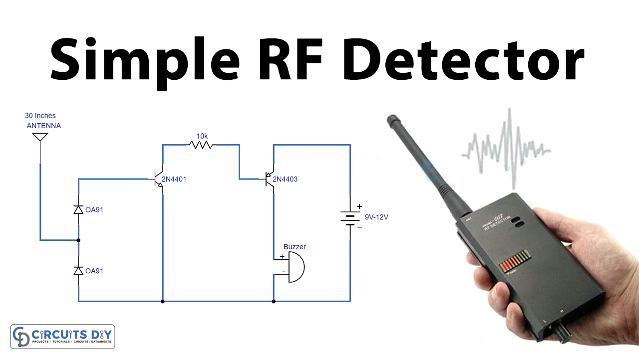
Simple RF Detector Circuit using Transistors
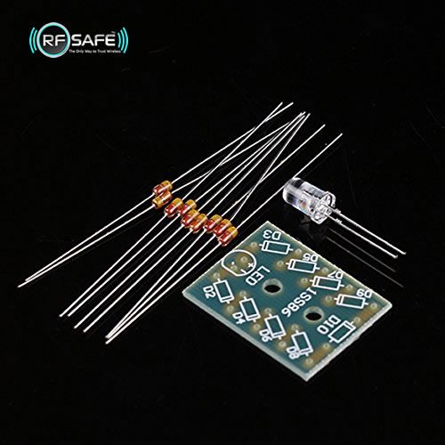
DIY RF METER LED IS 100 POWERED BY RF RADIATION USING DETECTOR DIODES
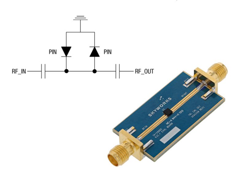
PIN diode protects RF receivers from 600 MHz to 6 GHz Electrical

SIMPLE RF PROBE Schematic included YouTube
Diode Probe

How to Make RF 📡 Detector YouTube
A Fast Switching Silicon Diode Like A 1N4148 Will Work, But Is The Least Sensitive Of Them All.
It Is Based On An Elektor.
A Passive Probe Works Where Relative Measurements Are.
The Layout Is Not Critical, But Do Make Sure You Get.
Related Post: